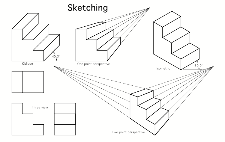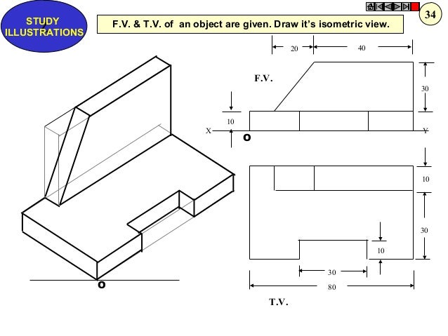

58a or 58b every visible edge of the object is shown in its true length just as in Fig. Accurate measurements may be made only along or parallel to these isometric lines. Of course edges A-B, A-C, etc., are foreshortened when the brick is turned into this position but since this distortion is not great, all isometric lines are drawn in their true length. These lines are known as Isometric Axes and all lines parallel to them are Isometric Lines. 58a or 58b so that edges A-B, A-C and A-D each make an angle of 120 degrees with the other. 57 then tilted up or down into either position shown in Fig. First it is turned so that the 2 by 8-inch face and the 2 by 4-inch face make angles of 45 degrees with the picture plane, Fig. See Plate 46.įor an illustration of this method, the brick has again been used and is considered to be 8 inches long, 4 inches wide and 2 inches high, Fig.

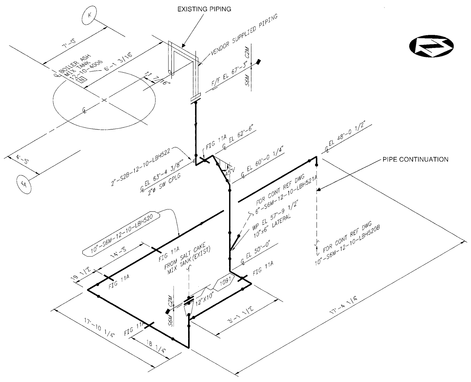
This pictorial method is seldom used to represent the building itself except that it is sometimes satisfactory for framing drawings. The usual Orthographic Projection drawing would be inadequate to show clearly and comprehensively such a system as a whole. In these the walls and floors are imagined to have been removed showing only the boilers, tanks, radiators, etc., with the connecting pipe lines all in the proper relation to each other. Such drawings are found useful to the architect in making pictorial diagrams of piping systems, etc., where artistic appearance is not a factor. This system then is used where approximate pictorial effect is desired together with the advantage of measuring distances directly on the picture.


Although the ability to measure distances on this kind of a picture is gained, there is somewhat of a loss in pictorial value, as the Isometric drawing does not show the object exactly as seen by the eye of the observer. To supply this need of an easily made picture upon which parts may be measured directly, we have a system of drawing called Isometric Drawing. This can not be done on a perspective as most of the distances are more or less distorted as has already been seen. While perspective projection is the method of pictorial representation generally used by the architectural draftsman, he sometimes finds it desirable to draw a quick mechanical picture on which he can measure most distances directly.


 0 kommentar(er)
